Winder Load Modelling
Related roll diameter, line speed, tension and winding torque, then scaled the operating variables to match the laboratory motor–generator setup.
PROJECT 02 / COURSE PROJECT
Reproducing winder speed and torque characteristics through digitally controlled electrical loading.
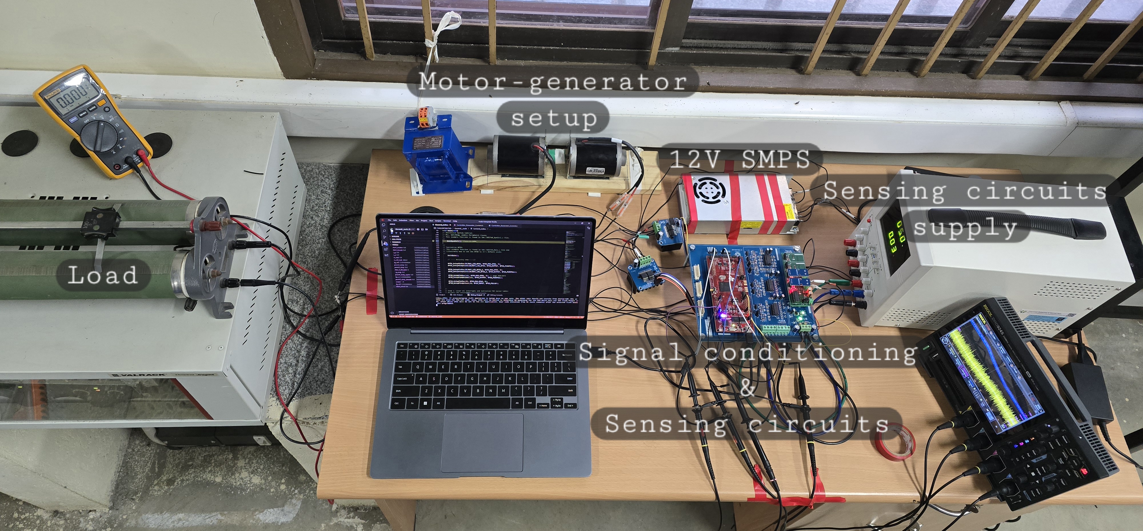
A PMDC motor–generator setup was used to emulate the changing load characteristics of a winder. In a winding process, increasing roll diameter requires higher torque and lower shaft speed to maintain constant material tension and line speed. The coupled generator provides a controllable electrical load that reproduces this behaviour without a physical winding roll.
The project combined system modelling, PI current-controller design, PLECS simulation, and hardware implementation using the TI TMS320F28379D. It was completed as part of the Digital Controller for Energy Conversion mini project at IIT Palakkad under the guidance of Dr. Arun Rahul S.
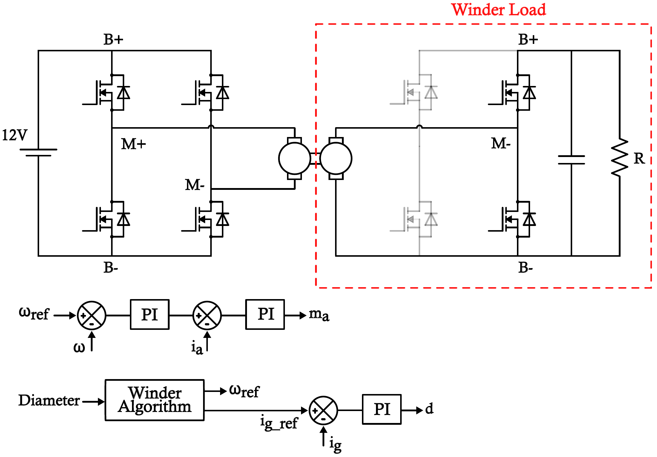
The setup uses two H-bridges, one on each side of the mechanically coupled PMDC motor–generator pair. The motor-side H-bridge drives the motor using cascaded speed and armature-current control loops. On the generator side, only two switches of the second H-bridge are used, with the PMDC machine’s armature-winding inductance providing the inductive energy storage. The generator-side circuit feeds a 20 Ω resistive load, and regulating generator current controls the opposing torque applied to the motor.
The winder algorithm calculates motor-speed and generator-current references from the changing roll diameter, assuming constant line speed and tension. As the emulated diameter grows, the speed reference decreases while the generator-current reference increases.
Related roll diameter, line speed, tension and winding torque, then scaled the operating variables to match the laboratory motor–generator setup.
Modelled the generator-side circuit, accounting for the PMDC machine’s armature-winding inductance, and derived a small-signal relationship between duty ratio and generator current. Designed a PI current controller using MATLAB SISO Tool.
Simulated the complete system in PLECS and implemented the control on the TI TMS320F28379D. Tested the hardware using sensed speed and current signals, reference signals, and oscilloscope measurements.
Before enabling the winder algorithm, the simulated motor operates at 280 rad/s with a generator-current reference of 0.6 A. After enabling the algorithm, the references gradually settle to 170 rad/s and 0.98 A, reproducing the decreasing-speed and increasing-torque behaviour of a growing winding roll.
The PLECS model and simulated tracking waveforms are included in the downloadable project presentation.
The hardware captures below show generator-current tracking and the combined speed and current profiles during winder emulation.
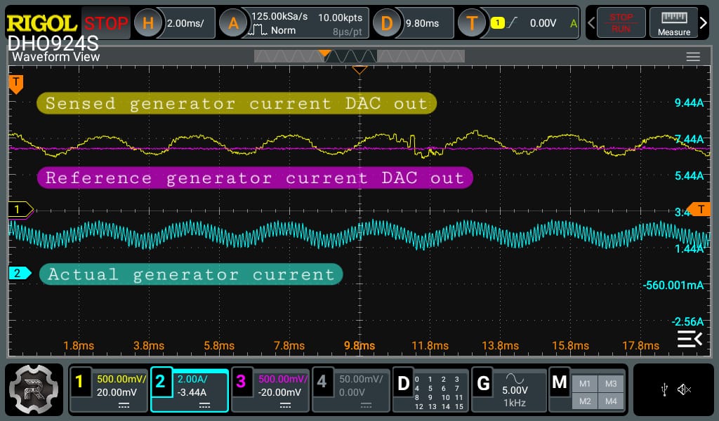
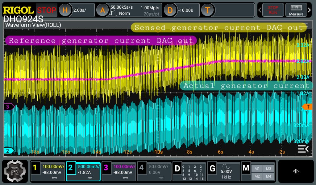
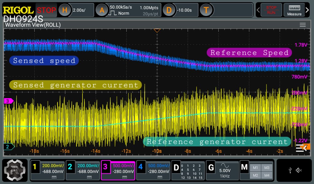
The PMDC motor–generator winder emulator was modelled, simulated, and implemented in hardware. Experimental waveforms demonstrate the intended decrease in motor speed and increase in generator loading, alongside generator-current controller tracking.