Model the converter
Simulate the synchronous buck power stage in MATLAB/Simulink and study its behaviour for the intended PV charging application.
PROJECT 02 / COURSE PROJECT
Extracting solar power through carefully designed control.
OVERVIEW
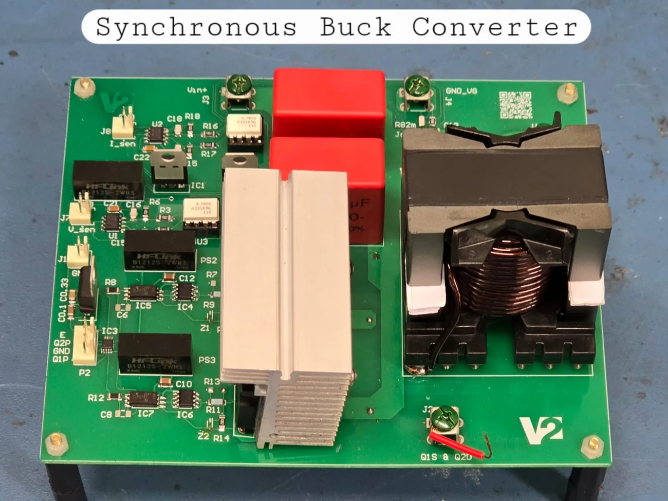
A synchronous buck converter was designed, simulated, and implemented to extract maximum power from a PV panel for a battery-charging application. The project connects converter and magnetics design with digitally implemented maximum power point tracking.
The work included MATLAB/Simulink simulation, PCB design in Altium Designer, inductor design and hand winding, Bode-plot-based PI-controller design, and digital MPPT implementation. It was completed for the Renewable Energy Systems course at IIT Palakkad under Dr. Naga Brahmendra Yadav Gorla.
DESIGN & IMPLEMENTATION
Simulate the synchronous buck power stage in MATLAB/Simulink and study its behaviour for the intended PV charging application.
Use the Bode-plot approach to select PI-controller constants. Design and hand-wind the inductor, then integrate the converter on a custom PCB.
Implement the Incremental Conductance algorithm on the TI C2000 development board to track the PV maximum power point.
PROJECT OUTCOME
The course project was successfully completed, combining simulation, controller design, magnetic-component construction, PCB development, and embedded control in one working hardware implementation.
View the project on LinkedIn ↗